What are the existing grounding resistance measurement methods?
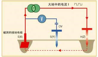
First, grounding resistance measurement A basic prerequisite for ensuring electrical safety in a home or factory is to provide a grounding electrode. Without a grounding electrode, personnel will be in danger and electrical equipment and other property will be damaged. However, a single ground electrode is not completely safe. Only regular inspections can ensure proper operation of the electrical installation. Second, why is grounding necessary? Therefore, grounding involves the use of a wire to connect a ground electrode to the metal chassis ground, which can introduce current from the electrical equipment due to insulation failure into the ground. With this method, since the fault current is introduced into the earth, there is no danger to the personnel. If there is no grounding, anyone who comes into contact may get an electric shock. If the current is large, it may be fatal. Third, the method of measuring the existing grounding resistance 1. Grounding resistance measurement of a single grounding electrode device It should be pointed out that all electrical installation test standards refer to the 2 ground pile method, which is a method of measuring the grounding resistance that is both accurate and safe. The measurement principle involves injecting an alternating current (I) using an appropriate power source G, through the auxiliary electrode H and back to the ground electrode E. The voltage between the ground electrode E and the point at which the ground potential is zero is measured using another auxiliary electrode S. The resistance can then be calculated by separate voltage measurements and constant current injection. 2, 3-pole measurement method (62% method) This method requires the use of 2 auxiliary electrodes (or "ground makeup") to inject current and provide a 0V potential reference. The position of the two auxiliary electrodes is critical to the ground electrode E(X) being tested. For correct measurement, the "0V potential auxiliary electrode" cannot be placed in the affected area to cause current (I) to circulate. Statistics show that the method to ensure high measurement accuracy is to set the pile SQ at a distance E62 from the EH line. It is then necessary to ensure that the local pile S has no change or slight change in the measurement results at the previous 10% distance from the initial position on the line EH. If the measurement varies greatly, this means that S is in the area of ​​influence, so the distance must be increased and the measurement repeated. 3, 4 pole grounding resistance measurement method The 4-pole grounding resistance measurement is based on the same principle of 3-pole measurement, but with a connection between the grounded electrode E and the measuring instrument. This method provides a better resolution (10 times higher than the 3-pole method) and means that wire resistance is no longer considered. 4, selective 4-pole grounding resistance measurement When a parallel grounding system is measured using a conventional 3-pole or 4-pole method, the measured current injected into the grounding system is distributed to different grounds. This means that the current of a given ground electrode cannot be determined, so its resistance cannot be determined. In such cases, this current is the total current in the grounded system under test, and the measured total ground resistance is equivalent to the resistance of all parallel grounded electrodes. In order to eliminate the effects of parallel ground electrodes, there is a variation of the 4-pole selectivity measurement method. The principle is the same except that a current clamp that measures the precise current on the ground being tested is added. The accuracy of the measured values ​​is guaranteed. 5. Ground loop measurement using 2 current clamps and measurement using a ground loop resistance clamp meter The advantage of the ground loop resistance clamp is that the setup is quick and easy: to measure the ground resistance and ground current, simply clamp the cable to the ground. The ground loop resistance clamp meter contains two coils: a "generator" coil and a "receiver" coil. - The "generator" coil of the clamp emits an alternating voltage with a constant voltage value of E around the enclosed conductor; then a current l = E/Rloop flows into the resistance loop. - The "receiver" coil measures the current. - Since E and I know, the loop resistance can be inferred. The raw material of the paper straw is white kraft paper, using two layers of 120g and one layer of 60g white kraft paper respectively. It is processed and produced with food-grade soybean-based oil ink and food-grade glue, which can be directly contacted with the human body and passed the FDA inspection. Paper Straw,Paper Drinking Straws,Cardboard Straws,Biodegradable Paper Straws NINGBO JINMAO IMPORT&EXPORT CO.,LTD , https://www.webrightsource.com