Case sharing | Three-dimensional ground penetrating radar used for highway inspection of the Ministry of Communications
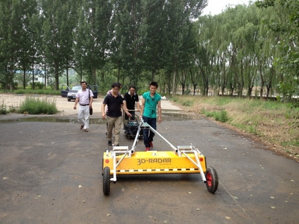
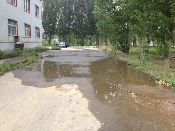
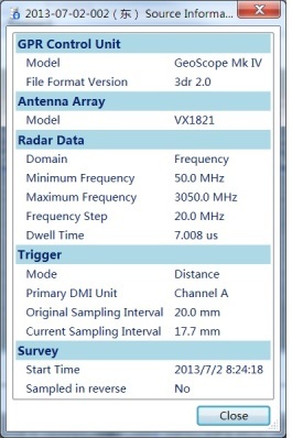
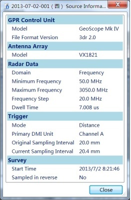
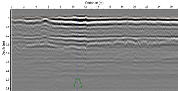
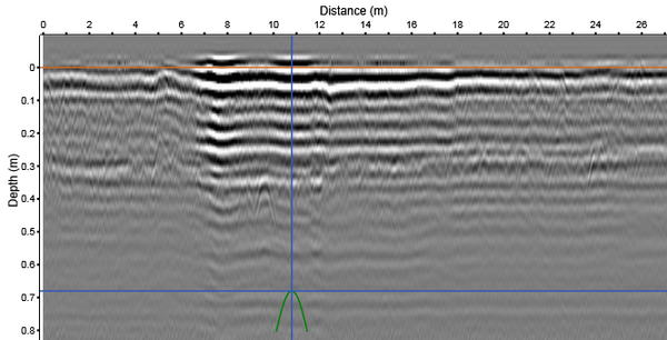
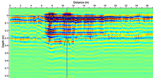
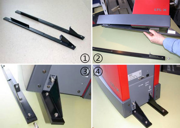
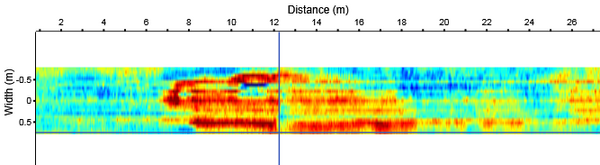
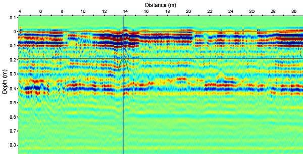
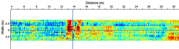
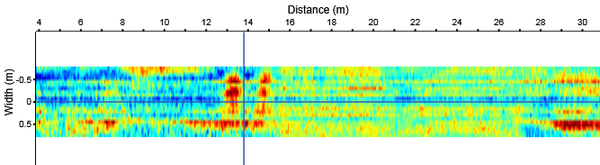
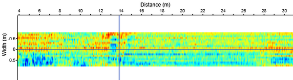
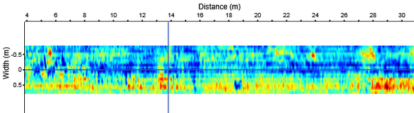
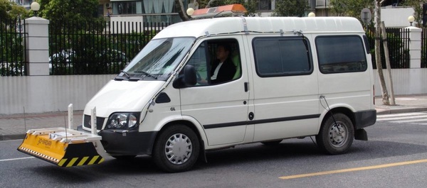
1 Project Overview The purpose of the test: to use the 3D ground penetrating radar of the United States 3D-Radar Company to carry out the research on the detection of asphalt pavement cracks and pavement substructures. Test location: Highway Test Site of the Ministry of Communications. Test equipment: 3D radar of the Ministry of Communications Highway Institute, host: GeoScope IV, antenna array: VX1821, which is 1.8 meters long, 21 pairs of antenna channels, antenna channel spacing is 7.5cm, air-coupled antenna, trailer installation. 2 Test section The length of the test road section is about 26 meters. Two data collection road sections have been made. The east road section (the side away from the warehouse) has obvious cracks at 7-18 meters, of which there is a piece of 5 X 0.8 square meters in the longitudinal section of 7-12 meters. The rice area sinks significantly. The west section (near the warehouse) was not damaged on the surface. Based on the principle of strong radar reflection in the water-bearing area, artificial watering was used during the test to make the water seep into the pavement and collect data when the pavement is obviously free of water. 3 Radar data acquisition settings Frequency setting: 50 MHz-3050 MHz, step frequency is 20 MHz; dwell time (transmission time of each frequency) is 7.008 microseconds; longitudinal sampling interval is about 2cm; The two acquisition settings are shown below: 4 Data analysis and data interpretation 3D-Radar's data analysis software 3dr-Examiner V2.80 was used for data analysis. Eastern data Comparison of the longitudinal sections of different channels: in the longitudinal 7-13 meter section, the typical longitudinal sections of the 3rd to 14th channels are shown in Figure 2. The typical longitudinal sections of the other channels are shown in Figure 1. It can be seen that the 3rd to 14th channels , According to the lateral distance between the channels is 7.5cm, the lateral distance of the abnormal area is 0.825 meters. This coincides with the visible sinking area of ​​the road surface. Because the dielectric constant of the core calibration medium is not taken, the following is based on the dielectric constant of 5 for estimation. The test section shows that the thickness of the asphalt layer of this section is about 5cm, and the distance between the water-stable layer and the road surface is about 30cm. The longitudinal section of Figure 3 shows that the reflection is stronger in the 7-18 meter section, even worse in the 7-13 meter section. This is related to cracks filled with water. 4 to 9 are horizontal views at different depths. Reflecting that the water-bearing area changes with depth, it can be roughly considered that the water-bearing area basically reaches the water-stable layer, and in the 13-18 m section, the water-bearing area is deeper. Figure 1. Longitudinal section of the first channel Figure 2. 8th channel longitudinal section Figure 3. Longitudinal view Figure 4. Horizontal slice of 6 cm depth Figure 5. Horizontal slice of 11.2 cm depth Figure 6. Horizontal slice of 25.0 cm depth Figure 7. Horizontal slice of 28.3 cm depth Figure 8. Horizontal slice of 30.1 cm depth Figure 9. Horizontal slice at 38.1 cm depth Western data The data of the western section is basically the same, and the longitudinal section is shown in Figure 10. Data analysis estimates that the thickness of the asphalt layer is about 5cm, which is the same as the east side road section, but the water stable layer is about 35cm away from the road surface, which is deeper than the east section. 10 to 16 are horizontal views at different depths. Compared with the data in the east section, the horizontal view of the west section shows that the medium is more uniform and there is no obvious high water area. Figure 10. Longitudinal view Figure 11. Horizontal slice at 6 cm depth Figure 12. Horizontal slice of 11.1 cm depth Figure 13. Horizontal slice of 25.6 cm depth Figure 14. Horizontal slice of 28.2 cm depth Figure 15. Horizontal slice of 32.5 cm depth Figure 16. Horizontal slice of 41 cm depth 5 in conclusion By comparing the radar data charts of the east and west sections, it can be seen that there are cracks and the waveform diagram of the sinking area is different. After the medium contains water, the radar detection effect will be significantly improved. It is a good method to try to collect data after rain and carry out 3D-Radar three-dimensional radar detection research on pavement cracks. 6 Introduction to GeoScope 3D Ground Penetrating Radar The GeoScope 3D ground penetrating radar system is a set of powerful and flexible underground non-destructive testing tools launched by the 3D-Radar company in the United States. It uses 3D ground penetrating radar to collect internal information on highways, airport runways, and municipal road structures to find out in advance Diseases such as air, water, and large-scale cracks and preventive maintenance are gradually becoming an important part of building a digital smart city. 3D Radar of the United States is leading the development of the industry as a global leader in this field. The three-dimensional radar system GeoScopeTM uses digital stepped frequency technology, which can be used for different applications, using different frequency ranges, and controlling the entire frequency spectrum through the acquisition software parameter settings, optimizing the relationship between the detection depth and the radar system resolution, thus Obtain the best image quality of the detection target; At the same time, GeoScope uses electronic scanning antenna array technology, which can carry out fast and accurate 3D survey, and realize true 3D detection; GeoScope acquisition software can display 3D images in real time, which is the only realization on the market at present Ground three-dimensional imaging ground penetrating radar system. Application field GeoScope is highly flexible and has an extremely wide range of applications, such as: Highway inspection Bridge panel inspection Underground pipeline survey and mapping Airport runway inspection Railway subgrade inspection archeology Landmine and unexploded object detection System advantages The host adopts innovative digital step frequency radar technology Antenna application leads the electronic scanning wireless array technology of GPR antenna design Real-time three-dimensional display of test data and analysis results The best equipment for high-resolution road NDT Europe and the United States is the sole distributor of 3D-Radar in China. If you need more information about the products, please feel free to call us ~ Bagasse Pulp Salad Container,Biodegradable Salad Bowl,Bagasse Pulp Salad Bowl,Sugarcane Fiber Salad Bowl EVER GREEN(ZHEJIANG)NEW MATERIAL CO., LTD / KUNSHAN GREENPACK CO.,LTD , https://www.zjchangjingpack.com